What is an orifice flange?
The Orifice Flange is used to measure how much product is flowing through the piping system. When the Orifice Plate is put in place, the flow is restricted. This makes a difference in pressure, which is used to measure how fast liquids, steam,or gasses are moving. The Orifice Plate is a thin plate with a hole in the middle. The size of the hole is based on the flow rate you want.
The traditional orifice flange assembly is made up of two flanges, an orifice plate, bolts, nuts, gaskets, jacking screws, and plugs. Jacking screws make it easy to get the primary flow element out of the way.
Orifice flanges are available in all ASTM forged grades (ASTM A105, ASTM A350, ASTM A694, and ASTM a182 for carbon, alloy, and stainless steel flanges, respectively), dimensions (combinations of nominal sizes and pressure ratings), and shapes (socket weld, threaded, or weld neck) (WN is the most used).
ORIFICE FLANGE MATERIAL GRADE AND FACINGS
Orifice Flange assemblies are available in all ASTM material grades and fall under ASME B16.36. They can have either a Raised Face or a Ring Type Joint facing. They aren’t made in 150# rated Flanges because they aren’t thick enough to let the pressure taps be drilled. Instead, they are made in 300#, 600#, 900#, 1500#, and 2500# Classes.
ORIFICE UNIONS
The Orifice Flange assemblies are made up of two Flanges, bolts, nuts, gaskets, jack screws, and plugs. The jack screws are used to put the Orifice Plate in place or take it out. Orifice Unions are the names for these groups of parts. To avoid turbulence at the Orifice Plate, the Orifice Flanges are installed in a straight run of pipe with ten pipe diameters upstream of the Orifice Plate and five pipe diameters downstream. The American Gas Association says this is the case.
Orifice flanges are a type of flange that are mostly used in the industrial world to measure how fast liquids, gases, or steam move through pipelines. They are often used in the oil and gas, chemical, and water treatment industries, where measuring flow accurately is important for the best results.
In this article, we’ll talk about what an orifice flange is, how it works, what it can be used for, and why it’s important for industrial operations to run smoothly.
Understanding Orifice Flange
An orifice flange is a special kind of flange that is put into a pipeline system to measure how fast a fluid is moving through it. It is made up of a plate with a hole in the middle and two flanges on either side. The orifice plate makes a drop in pressure that can be used to measure how fast the fluid is moving.
There are many different sizes, types of materials, and pressure ratings for orifice flanges. The flow rate and the size of the pipe are used to figure out the size of the orifice. The type of fluid going through the pipeline determines what kind of material is used to make the orifice flange. For instance, if the fluid is corrosive, the orifice flange must be made of a material that doesn’t corrode, like stainless steel.
What is the purpose of an orifice flange?
A pressure drop in the pipeline system is what makes an orifice flange work. As the fluid moves through the orifice plate, its speed goes up while the pressure goes down. The pressure drop is related to the flow rate, and it can be measured with pressure gauges on either side of the orifice plate.
Bernoulli’s equation can be used to figure out how fast the fluid is moving based on the difference in pressure across the orifice plate. The equation shows how the flow of a fluid is related to the drop in pressure across an orifice plate.
How Orifice Flanges Are Used
Most of the time, orifice flanges are used in pipeline systems to measure flow. They are used in many different fields, such as:
Oil and gas: Orifice flanges are used to measure how fast crude oil, natural gas, and other petroleum products flow.
Orifice flanges are used to measure the flow rate of chemicals and corrosive liquids in the chemical industry.
Orifice flanges are used in water treatment plants to measure the flow rate of water and waste water.
In addition to measuring flow, orifice flanges are also used in systems that lower pressure. In these systems, they help lower the pressure of the fluid flowing through the pipeline.
Orifice Flanges Have Some Pros
Orifice flanges have a number of advantages, such as:
– Accurate flow measurement: Orifice flanges make it possible to measure flow accurately, which is important for industrial operations to run smoothly.
– Cost-effective: Orifice flanges aren’t as expensive as flow meters or other devices used to measure flow.
– Easy to set up: Orifice flanges are easy to set up and don’t need much maintenance.
How to Install an Orifice Flange
To measure flow accurately, orifice flanges must be installed correctly. The orifice plate needs to be in the middle of the pipeline, and the flanges need to be tightened to the right torque. To measure pressure correctly, the pressure taps on either side of the orifice plate must also be installed correctly.
Flange dimensions 150 refer to the size of the flange as per ANSI/ASME standards. This flange size is commonly used in various industrial applications, including petrochemical, chemical, and oil and gas industries.
The dimensions of flange 150 are as follows:
-The nominal size of the flange is 1.5 inches (38.1 mm)
-The outer diameter of the flange is 5.0 inches (127 mm)
-The bolt circle diameter is 3.88 inches (98.6 mm)
-The number of bolt holes is four
-The diameter of bolt holes is 0.62 inches (15.7 mm)
-The thickness of the flange is 0.88 inches (22.4 mm)
-It is important to note that these dimensions are specific to flange 150 and may vary for other flange sizes.
The flange 150 is designed to withstand high pressure and temperature, making it suitable for various industrial applications. It is typically made of materials such as carbon steel, stainless steel, and alloy steel, depending on the specific application requirements.
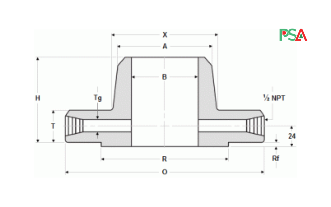
WELD NECK RF, CLASS 300
| NPS | A | R | O | T | H | X | Tg |
| 1 | 33.4 | 50.8 | 125 | 36.6 | 81 | 54 | 6.4 |
| 1½ | 48.3 | 73 | 155 | 36.6 | 84 | 70 | 6.4 |
| 2 | 60.3 | 92.1 | 165 | 36.6 | 84 | 84 | 6.4 |
| 2½ | 73 | 104.8 | 190 | 36.6 | 87 | 100 | 6.4 |
| 3 | 88.9 | 127 | 210 | 36.6 | 87 | 117 | 9.5 |
| 4 | 114.3 | 157.2 | 255 | 36.6 | 90 | 146 | 12.7 |
| 6 | 168.3 | 215.9 | 320 | 36.6 | 98 | 206 | 12.7 |
| 8 | 219.1 | 269.9 | 380 | 39.7 | 110 | 260 | 12.7 |
| 10 | 273 | 323.8 | 445 | 46.1 | 116 | 321 | 12.7 |
| 12 | 323.8 | 381 | 520 | 49.3 | 129 | 375 | 12.7 |
| 14 | 355.6 | 412.8 | 585 | 52.4 | 141 | 425 | 12.7 |
| 16 | 406.4 | 469.9 | 650 | 55.6 | 144 | 483 | 12.7 |
| 18 | 457 | 533.4 | 710 | 58.8 | 157 | 533 | 12.7 |
| 20 | 508 | 584.2 | 775 | 62 | 160 | 587 | 12.7 |
| 24 | 610 | 692.2 | 915 | 68.3 | 167 | 702 | 12.7 |
| NPS | Bolt Diameter | # Bolts | Bolt holes diameter | Bolts Diameter | Bolts length mm. |
| 1 | 88.9 | 4 | 11/16 | 5/8 | 125 |
| 1½ | 114.3 | 4 | 13/16 | 3/4 | 135 |
| 2 | 127 | 8 | 11/16 | 5/8 | 125 |
| 2½ | 149.2 | 8 | 13/16 | 3/4 | 135 |
| 3 | 168.3 | 8 | 13/16 | 3/4 | 135 |
| 4 | 200 | 8 | 13/16 | 3/4 | 135 |
| 6 | 269.9 | 12 | 7/8 | 3/4 | 135 |
| 8 | 330.2 | 12 | 1 | 7/8 | 145 |
| 10 | 387.4 | 16 | 1 1/8 | 1 | 165 |
| 12 | 450.8 | 16 | 1¼ | 1 1/8 | 180 |
| 14 | 514.4 | 20 | 1¼ | 1 1/8 | 185 |
| 16 | 571.5 | 20 | 1 3/8 | 1¼ | 195 |
| 18 | 628.6 | 24 | 1 3/8 | 1¼ | 205 |
| 20 | 685.8 | 24 | 1 3/8 | 1¼ | 215 |
| 24 | 812.8 | 24 | 1 3/8 | 1½ | 240 |
WELD NECK RF, CLASS 600
| NPS | A | R | O | T | H | X | Tg |
| 1 | 33.5 | 50.8 | 125 | 36.6 | 81 | 54 | 6.4 |
| 1½ | 48.3 | 73 | 155 | 36.6 | 84 | 70 | 6.4 |
| 2 | 60.3 | 92.1 | 165 | 36.6 | 84 | 84 | 6.4 |
| 2½ | 73 | 104.8 | 190 | 36.6 | 87 | 100 | 6.4 |
| 3 | 88.9 | 127 | 210 | 36.6 | 87 | 117 | 9.5 |
| 4 | 114.3 | 157.2 | 275 | 38.1 | 102 | 152 | 12.7 |
| 6 | 168.3 | 215.9 | 355 | 47.7 | 117 | 222 | 12.7 |
| 8 | 219.1 | 269.9 | 420 | 55.6 | 133 | 273 | 12.7 |
| 10 | 273 | 323.8 | 510 | 63.5 | 152 | 343 | 12.7 |
| 12 | 323.8 | 381 | 560 | 66.7 | 156 | 400 | 12.7 |
| 14 | 355.6 | 412.8 | 605 | 69.9 | 165 | 432 | 12.7 |
| 16 | 406.4 | 469.9 | 685 | 76.2 | 178 | 495 | 12.7 |
| 18 | 457.2 | 533.4 | 745 | 82.6 | 184 | 546 | 12.7 |
| 20 | 508 | 584.2 | 815 | 88.9 | 190 | 610 | 12.7 |
| 24 | 609.6 | 692.2 | 940 | 101.6 | 203 | 718 | 12.7 |
| NPS | BOLT CIRCLE DIAM. | BOLTS # | HOLES DIAM. | BOLTS DIAMETER | BOLTS LENGTH |
| 1 | 88.9 | 4 | 11/16 | 5/8 | 125 |
| 1½ | 114.3 | 4 | 13/16 | 3/4 | 135 |
| 2 | 127 | 8 | 11/16 | 5/8 | 125 |
| 2½ | 149.2 | 8 | 13/16 | 3/4 | 135 |
| 3 | 168.3 | 8 | 13/16 | 3/4 | 135 |
| 4 | 215.9 | 8 | 1 | 7/8 | 150 |
| 6 | 292.1 | 12 | 1 1/8 | 1 | 180 |
| 8 | 349.2 | 12 | 1¼ | 1 1/8 | 195 |
| 10 | 431.8 | 16 | 1 3/8 | 1¼ | 220 |
| 12 | 489 | 20 | 1 3/8 | 1¼ | 230 |
| 14 | 527 | 20 | 1½ | 1 3/8 | 240 |
| 16 | 603.2 | 20 | 1 5/8 | 1½ | 260 |
| 18 | 654 | 20 | 1 3/4 | 1 5/8 | 280 |
| 20 | 723.9 | 24 | 1 3/4 | 1 5/8 | 300 |
| 24 | 838.2 | 24 | 2 | 1 5/8 | 335 |
COMMENTS: Height of Raised Face (RF) in CLASS 600 is 2 mm at NPS 1 – NPS 3, and 7 mm at NPS 4 – NPS 24.
WELD NECK RF, CLASS 900

| NPS | R | O | T | H | X | A | Tg |
| 1 | 50.8 | 125 | 36.6 | 81 | 54 | 33.5 | 6.4 |
| 1½ | 73 | 155 | 36.6 | 84 | 70 | 48.3 | 6.4 |
| 2 | 92.1 | 165 | 36.6 | 84 | 84 | 60.3 | 6.4 |
| 2½ | 104.8 | 190 | 36.6 | 87 | 100 | 73 | 6.4 |
| 3 | 127 | 240 | 38.1 | 102 | 127 | 88.9 | 9.5 |
| 4 | 157.2 | 290 | 44.5 | 114 | 159 | 114.3 | 12.7 |
| 6 | 215.9 | 380 | 55.6 | 140 | 235 | 168.3 | 12.7 |
| 8 | 269.9 | 470 | 63.5 | 162 | 298 | 219.1 | 12.7 |
| 10 | 323.8 | 545 | 69.9 | 184 | 368 | 273 | 12.7 |
| 12 | 381 | 610 | 79.4 | 200 | 419 | 323.8 | 12.7 |
| 14 | 412.8 | 640 | 85.8 | 213 | 451 | 355.6 | 12.7 |
| 16 | 469.9 | 705 | 88.9 | 216 | 508 | 406.4 | 12.7 |
| 18 | 533.4 | 785 | 101.6 | 229 | 565 | 457.2 | 12.7 |
| 20 | 584.2 | 855 | 108 | 248 | 622 | 508 | 12.7 |
| 24 | 692.2 | 1040 | 139.7 | 292 | 749 | 609.6 | 12.7 |
| NPS | BOLT CIRCLE DIAM. | BOLTS # | HOLES DIAM. | BOLTS DIAMETER | BOLTS LENGTH |
| 1 | 88.9 | 4 | 11/16 | 5/8 | 125 |
| 1½ | 114.3 | 4 | 13/16 | 3/4 | 135 |
| 2 | 127 | 8 | 11/16 | 5/8 | 125 |
| 2½ | 149.2 | 8 | 13/16 | 3/4 | 135 |
| 3 | 190.5 | 8 | 1 | 7/8 | 150 |
| 4 | 235 | 8 | 1¼ | 1 1/8 | 180 |
| 6 | 317.5 | 12 | 1¼ | 1 1/8 | 195 |
| 8 | 393.7 | 12 | 1½ | 1 3/8 | 230 |
| 10 | 469.9 | 16 | 1½ | 1 3/8 | 240 |
| 12 | 533.4 | 20 | 1½ | 1 3/8 | 260 |
| 14 | 558.8 | 20 | 1 5/8 | 1½ | 280 |
| 16 | 616 | 20 | 1 3/4 | 1 5/8 | 290 |
| 18 | 685.8 | 20 | 2 | 1 7/8 | 330 |
| 20 | 749.3 | 20 | 2 1/8 | 2 | 355 |
| 24 | 901.7 | 20 | 2 1/8 | 2½ | 445 |
WELD NECK RF, CLASS 1500
| NPS | R | O | T | H | X | A | Tg |
| 1 | 50.8 | 150 | 38.1 | 83 | 52 | 33.5 | 6.4 |
| 1½ | 73 | 180 | 38.1 | 89 | 70 | 48.3 | 6.4 |
| 2 | 92.1 | 215 | 38.1 | 102 | 105 | 60.3 | 6.4 |
| 2½ | 104.8 | 245 | 41.3 | 105 | 124 | 73 | 6.4 |
| 3 | 127 | 265 | 47.7 | 117 | 133 | 88.9 | 9.5 |
| 4 | 157.2 | 310 | 54 | 124 | 162 | 114.3 | 12.7 |
| 6 | 215.9 | 395 | 82.6 | 171 | 229 | 168.3 | 12.7 |
| 8 | 269.9 | 485 | 92.1 | 213 | 292 | 219.1 | 12.7 |
| 10 | 323.8 | 585 | 108 | 254 | 368 | 273 | 12.7 |
| 12 | 381 | 675 | 123.9 | 283 | 451 | 323.8 | 12.7 |
| 14 | 412.8 | 750 | 133.4 | 298 | 495 | 355.6 | 12.7 |
| 16 | 469.9 | 825 | 146.1 | 311 | 552 | 406.4 | 12.7 |
| 18 | 533.4 | 915 | 162 | 327 | 597 | 457.2 | 12.7 |
| 20 | 584.2 | 985 | 177.8 | 356 | 641 | 508 | 12.7 |
| 24 | 692.2 | 1170 | 203.2 | 406 | 762 | 609.6 | 12.7 |
| NPS | BOLT CIRCLE DIAM. | BOLTS # | HOLES DIAM. | BOLTS DIAMETER | BOLTS LENGTH |
| 1 | 101.6 | 4 | 1 | 7/8 | 150 |
| 1½ | 123.8 | 4 | 1 1/8 | 1¼ | 160 |
| 2 | 165.1 | 8 | 1 | 7/8 | 150 |
| 2½ | 190.5 | 8 | 1 1/8 | 1 | 165 |
| 3 | 203.2 | 8 | 1¼ | 1 1/8 | 185 |
| 4 | 241.3 | 8 | 1 3/8 | 1¼ | 205 |
| 6 | 317.5 | 12 | 1½ | 1 3/8 | 265 |
| 8 | 393.7 | 12 | 1 3/4 | 1 5/8 | 300 |
| 10 | 482.6 | 12 | 2 | 1 7/8 | 345 |
| 12 | 571.6 | 16 | 2 1/8 | 2 | 380 |
| 14 | 635 | 16 | 2 3/8 | 2¼ | 415 |
| 16 | 704.8 | 16 | 2 5/8 | 2½ | 450 |
| 18 | 774.7 | 16 | 2 7/8 | 2 3/4 | 500 |
| 20 | 831.8 | 16 | 3 1/8 | 3 | 545 |
| 24 | 990.6 | 16 | 3 5/8 | 3½ | 620 |
WELD NECK RF, CLASS 2500
| NPS | R | O | T | H | X | A | Tg |
| 1 | 50.8 | 160 | 38.1 | 92 | 57 | 33.5 | 6.4 |
| 1½ | 73 | 205 | 44.5 | 111 | 79 | 48.3 | 6.4 |
| 2 | 92.1 | 235 | 50.8 | 127 | 95 | 60.3 | 6.4 |
| 2½ | 104.8 | 265 | 57.2 | 143 | 114 | 73 | 6.4 |
| 3 | 127 | 305 | 66.7 | 168 | 133 | 88.9 | 9.5 |
| 4 | 157.2 | 355 | 76.2 | 190 | 165 | 114.3 | 12.7 |
| 6 | 215.9 | 485 | 108 | 273 | 235 | 168.3 | 12.7 |
| 8 | 269.9 | 550 | 127 | 318 | 305 | 219.1 | 12.7 |
| 10 | 323.8 | 675 | 165.1 | 419 | 375 | 273 | 12.7 |
| 12 | 381 | 760 | 184.2 | 464 | 441 | 323.8 | 12.7 |
| NPS | BOLT CIRCLE DIAM. | BOLTS # | HOLES DIAM. | BOLTS DIAMETER | BOLTS LENGTH |
| 1 | 108 | 4 | 1 | 7/8 | 150 |
| 1½ | 146 | 4 | 1¼ | 1 1/8 | 180 |
| 2 | 171.4 | 8 | 1 1/8 | 1 | 185 |
| 2½ | 196.8 | 8 | 1¼ | 1 1/8 | 205 |
| 3 | 228.6 | 8 | 1 3/8 | 1¼ | 230 |
| 4 | 273 | 8 | 1 5/8 | 1½ | 260 |
| 6 | 368.3 | 8 | 2 1/8 | 2 | 350 |
| 8 | 438.2 | 12 | 2 1/8 | 2 | 385 |
| 10 | 539.8 | 12 | 2 5/8 | 2½ | 490 |
| 12 | 619.1 | 12 | 2 7/8 | 2 3/4 | 540 |
Recent Comments